Water wheels and drive shafts
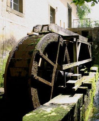 The mill is equipped with two waterwheels for two separately running grinding pairs (coarse and fine flour). They have a diameter of 3.20m and a width of approximately 80cm. Being different types of construction one wheel carries 32, the other 36 water shovels. Both wheels are reconstructions based on drawings from 1923 and are made of oak wood as well as metal (V2A) for the shovels. The average output per wheel is about 4.5 – 5.9 kW (6-8hp).
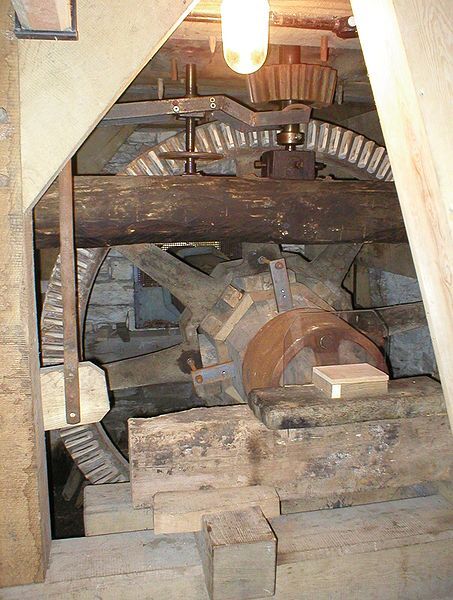
The torque (approx. 4000Nm) of the waterwheels is transmitted to the inside of the mill via octagonal shafts. The shafts are made of oak logs with a diameter of about 50cm. The weight of each shaft almost reaches 1500kg.
The pairs of stones
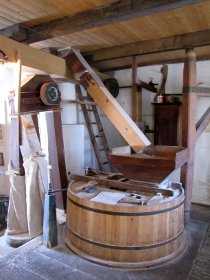 The heart of every flour mill are the milling processes. The Schäferkämper mill has one grinding pair for food and baking grist and a second one with a downstream classifier for fine flour. The grinding passages with the heavy millstones are located on the ground floor on the mill frame, the so-called hurst floor. Below this heavy oak construction is the angle gear, i.e. the engageable gear wheels, which turn the horizontal rotation of the mill wheels into a vertical one.
After the renovation and refurbishment in 1994, this area has become easily accessible to visitors.
Interestingly, the entire mill technics rest on a seperate foundation. This means that the forces occurring during operation are not transferred to the entire building.
The millstones
 Each grinding pair has two millstones lying on top of each other. The lower one is called bedstone. It is firmly anchored to the mill platform. Its absolute horizontal position is adjustable by three screws. The upper stone, also called runner, is adjustable in height. Thereby, one is able to vary the distance to the bedstone which allows for full control of the grist’s extraction rate.
The left shot barrel has a diameter of 1.50m, the right one is 1.30m. Each millstone has a weight of approximately 1000kg. Three of the original millstones have been reused during the renovation.
Vat, vibrating shoe and funnel
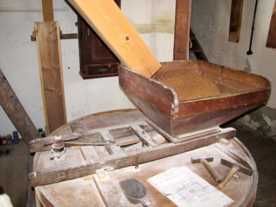 The entire grinding process takes place between the millstones, covered by a wooden hood. This vat serves as a dust-tight closure. From above, grain is fed through the so-called hull funnel in the middle of the upper stone. A vibrating shoe below the funnel opening ensures that the grain flows evenly. At the sides, the grist falls out between the stones and either collects in a tied bag or is fed to a further refining process via a lift mechanism.
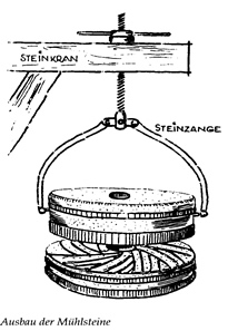
The tentering arrangement
 An important component of every grinding pair is the tentering arrangement, with which the miller was able to adjust the clear distance between the two millstones with millimetre precision. This was necessary in order to adjust the correct degree of milling of the flour. In order to be able to lift the heavy load of mill wheel, mill iron, bearings, pulleys and beams, a triple lever transmission (1:2; 1:1.3; 1:1.35) was implemented in the cellar. This is moved at the top from the grinding platform directly next to each grinding cycle with a hand crank in a transmission ratio of 1:33. Thus it is possible to lift the weight of about 1500kg at the crank with a manual force of about 130N. The flat pitch of the spindle thread provides an effective self-locking effect for lowering the weight.
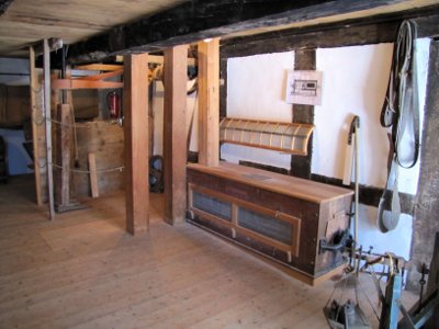
Elevators and separators
 For strongly milled fine flour, the dietary fibres must be sieved out. The technology installed for this purpose in the Schäferkämper Mill with a large elevator over three floors and a rotary classifier was probably installed at the beginning of the 20th century.
At the right fine-flour milling pair the flour does not fall into a bag but is transported via the bucket elevator to the attic of the mill. There, at top dead center, the buckets empty into the inlet channel of the classifier.
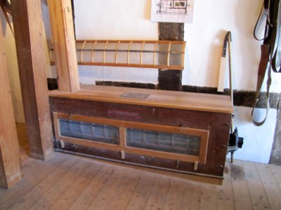 The separator works similar to a horizontally operated salad spinner. The grist is pressed against a fine-meshed sieve by fast rotating beaters. Fine flour particles pass through and collect at the bottom where a screw transports the fine flour to the filling point. The coarse particles are removed and used as animal food.
The drive of the complex mechanical elements with the exposed transmission belts can best be seen on the classifier floor.
Material flow
 Smaller quantities of grain were poured by hand directly into the hull funnel of a milling tunnel. Larger quantities were transported by a belt-driven bag elevator either inside or outside the mill to the first floor on the classifier floor. From there, the miller could shovel the grain through a filler neck from above into the hull hopper.
Flour and grain sacks could be stored on each floor of the mill using the sack elevator. The floor hatches, which were typical for grain mills and which ran from top to bottom, served this purpose.
The freight elevator
 The freight elevator is installed on the top floor of the mill and from there it enables the transport of material between the floors. This is possible both outside the building and inside through floor hatches.
It is driven by the stone shaft (central drive shaft) of the fine grinding pair, which is extended to the attic. The rotation is horizontally guided by a cast-iron angular gear and slowed down in a ratio of 2:1. A belt drive (1:2) brings the movement over a distance of about 2m to the winding shaft of the load chain.
 The transmission belt is dimensioned for full slip and is manually tensioned by means of a cable pull with a pressure roller. The lifting process can be gently started and braked at this control cable. Loads are lifted at about 1m/s. A controlled lowering of the lift is not possible. In this case the chain must be pulled downwards in the uncoupled state.
In order to avoid unnecessary idling of the elevator gear during pure grinding operation, the upper part of the mill iron, which is only inserted, can be raised and lowered with a simple rope wrap.
Historical modernizations
Around 1900, the order situation for the Schäferkämper Mill must have been so good that water power alone was no longer sufficient. After about 1 hour of work on both grinding pairs, the mill had to wait another 3-4 hours until the mill pond was filled up again. At this time the owner at that time bought a locomobile (a mobile steam engine). It was fired with wood or coal. This engine stood outside the building, where the extension is located today. The power of the locomobile was fed via belt drives to the vertical stone spindle of the fine-flour pair. For this purpose a hole had to be punched through the outer wall, which can still be seen today.
In addition, the locomobile also served as a drive for a simple wood saw.
Some years later the steam engine was replaced by an electric motor. Thus miller Thiemann was one of the first craftspersons using an electric aggregate in Westernkotten.